Refit of the on-board electrical system around the central circuit distribution and protection, carried out in winter 2019/2020.
1. Clean up and analysis
In the fall of 2019, the decision was made to equip the yacht with a Furuno DRS4D-NXT radar and a navigation computer, primarily to increase the safety level and to maximize the potential of the Timezero software. For the radar antenna, a Scanstrut radar mast with semi-gimbal mount will be installed at the stern, primarily to provide useful radar coverage over the entire horizon even when sailing with attitude. The computer with 22 inch monitor will be placed in the navi-corner, but this will require some modifications.
Although the existing components of the navigation electronics were all acquired or replaced after the purchase of the ship in 2011 and are therefore more recent, their arrangement was not systematic, but rather due to the available space and the simplest possible installation.
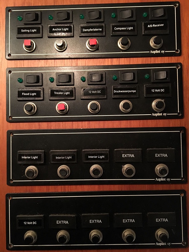
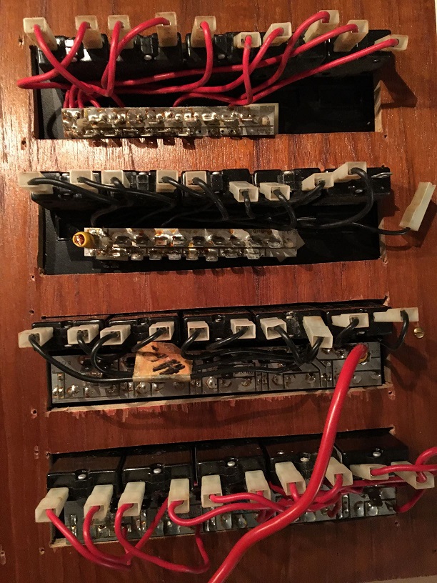
In particular, the wiring around the old fuse panels and circuit distributors had grown and was confusing. The cable chaos in the distribution cabinet has always bothered me. On the old fuse panels, most of the cables are directly soldered on, plus and minus connections are not insulated and very close to each other. The control cabinet in the nav corner is full of wildly routed cables, some of which end blindly on luster terminals or are simply cut off. One thick strand disappears behind the cabinet in an inaccessible area.
So the task is to replace the old front panel, fuse and switch panels and to rearrange all the old and additional new components and to fuse and wire them in their own circuits.
First, all old components, including the control panel and fuse panel, are removed from the front panel and the control cabinet, and important details of the wiring, for example, are documented.
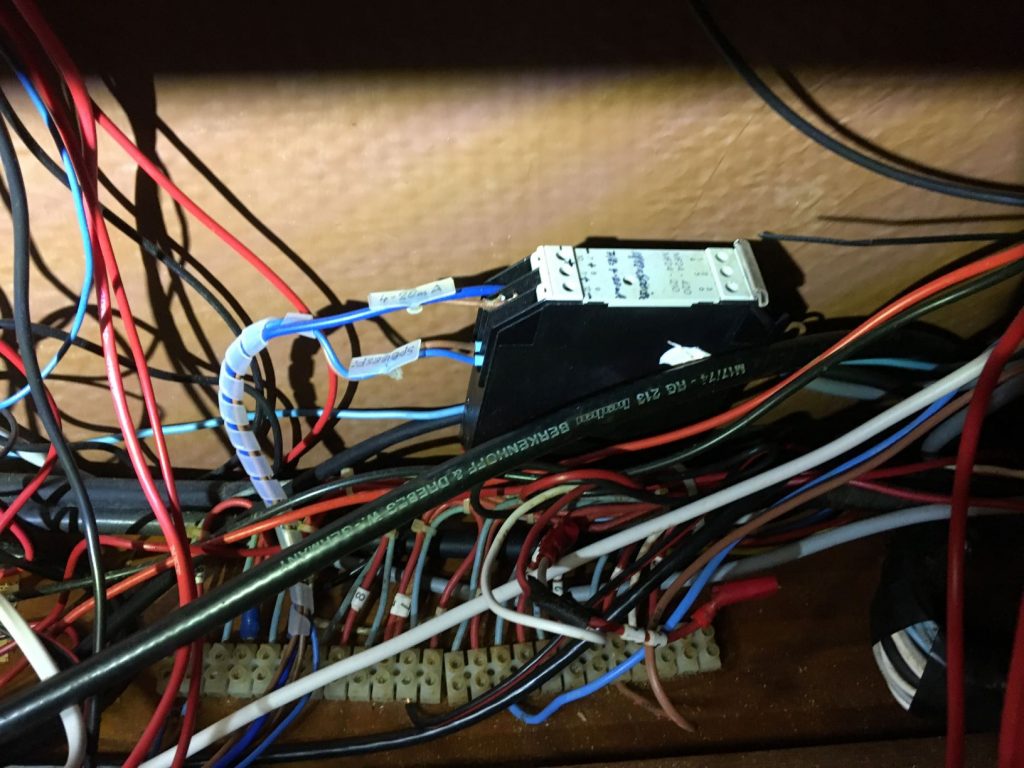
The old cables from the shipyard installation carry numbers and there is also shipyard documentation on the wiring. However, an initial check quickly reveals that more than half of the old documented wiring is no longer correct. In addition, there is the wiring for new components that has been added over the course of time, which of course is not documented at all, but results exclusively from the given wiring.
After an initial review, at least the positive lines for all consumers can be clearly identified.
However, it is often difficult to identify/assign the negative/ground lines for the consumers installed in the shipyard, because some of them do not even appear individually in the control cabinet, but simply all disappear in a thick cable harness without being able to be assigned to individual consumers. The wiring of the components added later, on the other hand, is clear and easy to understand.
During the removal of all components, all cables are labeled according to their assignment as far as possible.
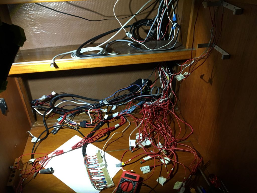
In the end, it turns out that about half of the old wiring on the shipyard side has no function at all. The thick cable harness wrapped with insulating tape, which disappears behind the nav table, turns out to be in parts the wiring of the negative/ground cables, which is realized on a small panel, which is then packed in the thick cable jumble. Nice mess …
After this cleanup, it’s first clear which cables still have a function and need to be reused, and where there’s room for the components to be installed. About half of the old wiring can go and is put separately in its own cable organizer out of the way. Another challenge is to determine which positive and negative wires belong together to a consumer.
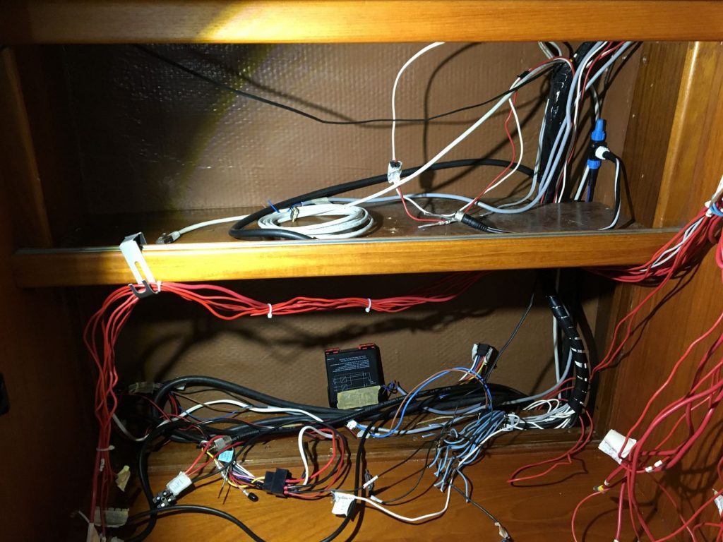
To some extent, this can be determined by measurements, but only where the consumers are also within range and can be switched on. All consumers on the mast are not within range, because the ship is in the hall and the mast is in the mast store. After some searching and trying, all required cables are finally identified and provisionally labeled.
The front of the lower part of the control cabinet is set back a bit on the shipyard side and can be pulled forward by about 8 cm, which creates valuable space.
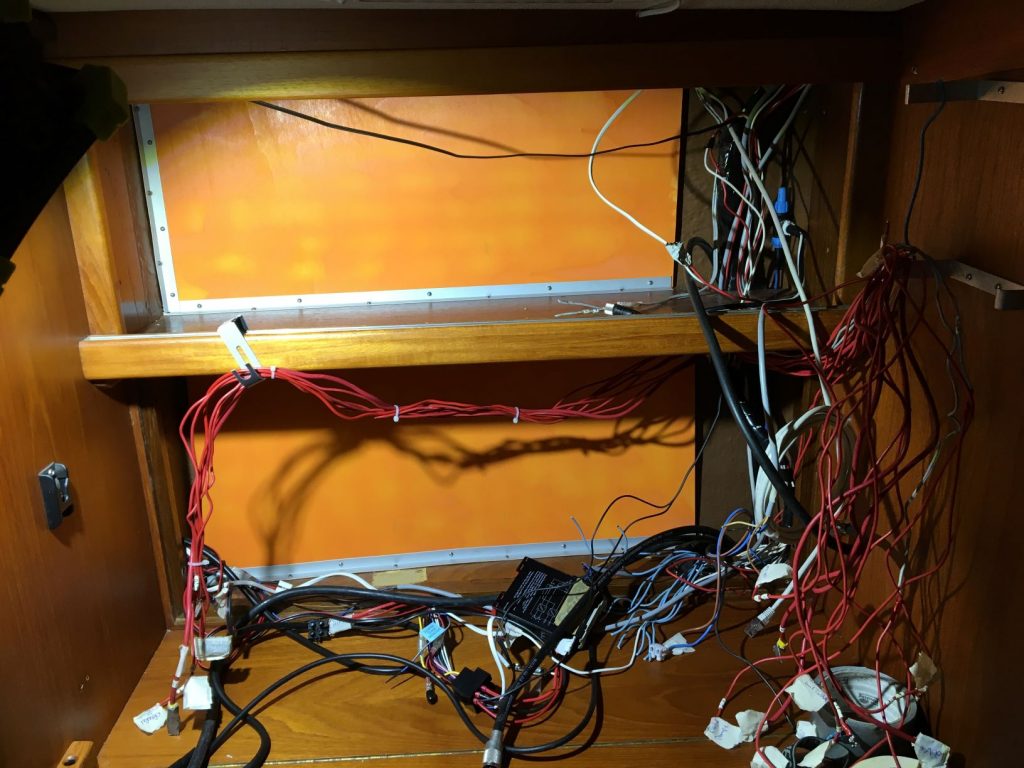
A light plywood panel is firmly attached to the back, which allows different components to be attached easily and quickly. Now, on this light background, the old and new components are to be rearranged and mounted so that a neat and clear installation is created.
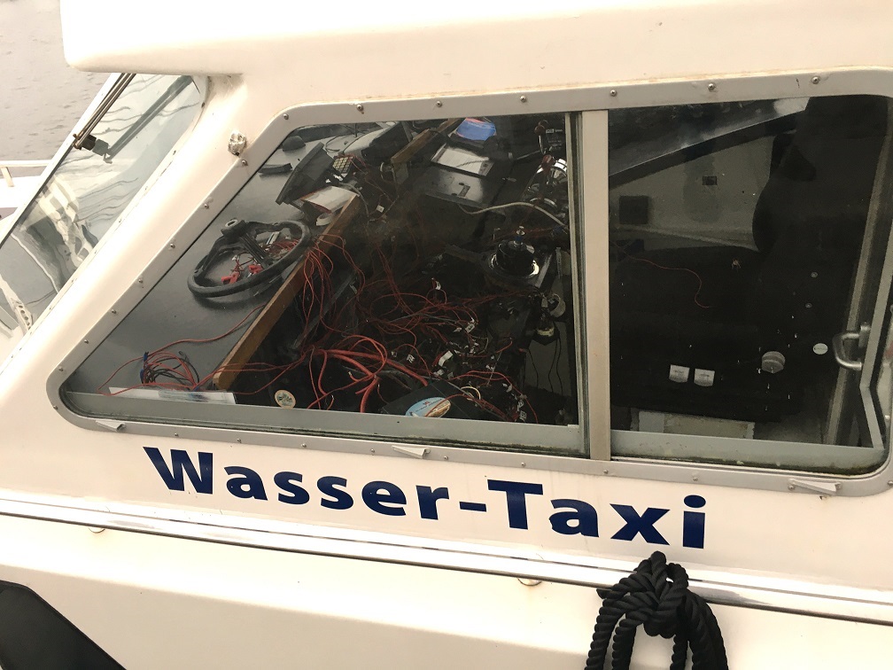
btw: with the professionals it often doesn’t look any better … 😉
2. Installation and wiring
The next step is to place and install all components that do not fit on the front panel: DC converter, AIS transponder, NMEA distributor, LAN and WLAN components. Computer follows later, because not yet delivered. The position of the components determines the optimal cable routing, for which special cable organizers with different diameters are installed.
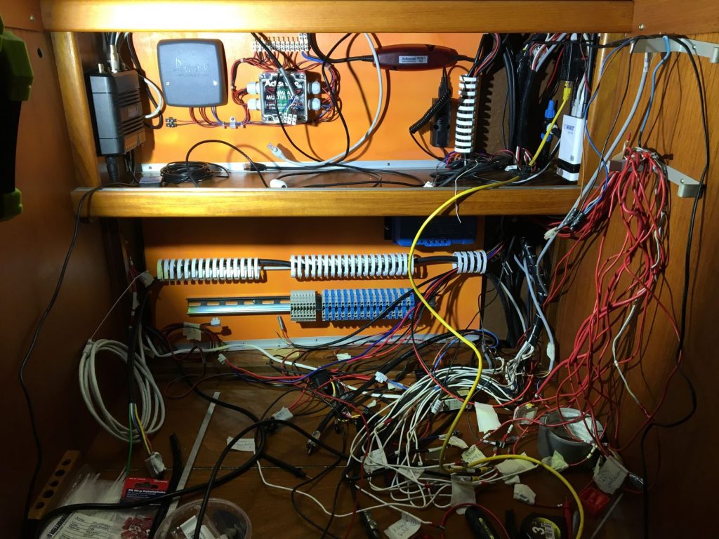
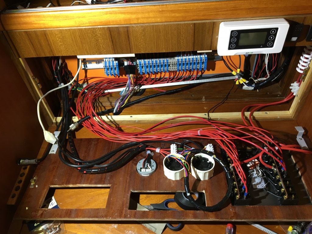
Then, directly underneath the main line, a terminal rail with various terminal blocks between 4 and 6 mm2 for plus/minus connections is attached, which can thus be wired well and directly from the main line and in the direct vicinity of the later main power distribution panel in the front panel on a short and direct path with it.
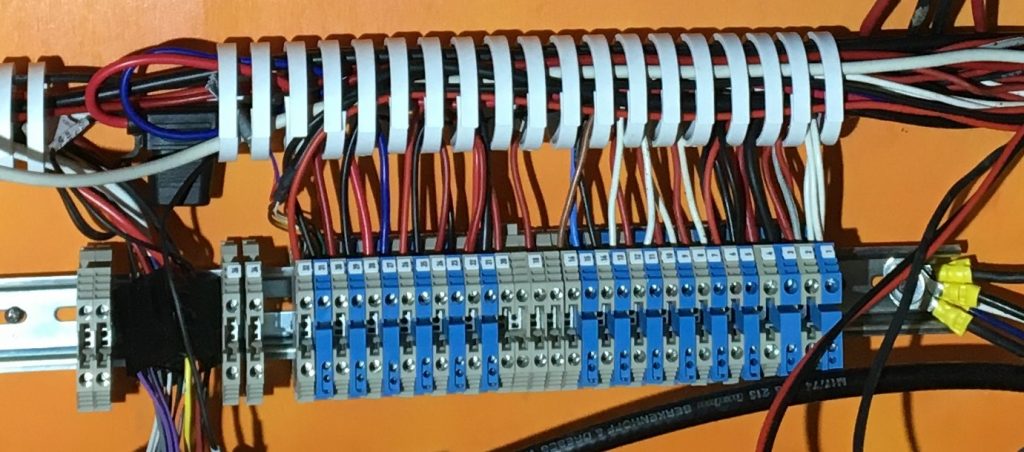
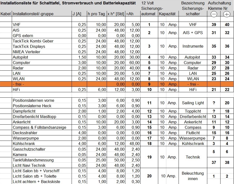
The terminals are numbered and so the assignment of the circuits can be documented very easily. The plus side is later connected to the circuit breakers of the switch panel and so the individual circuits are fused via the terminals and can be switched. Now the wiring and labeling of the individual terminal blocks is done step by step. First of all the consumer side, so that the cable tangle is gradually cleared.
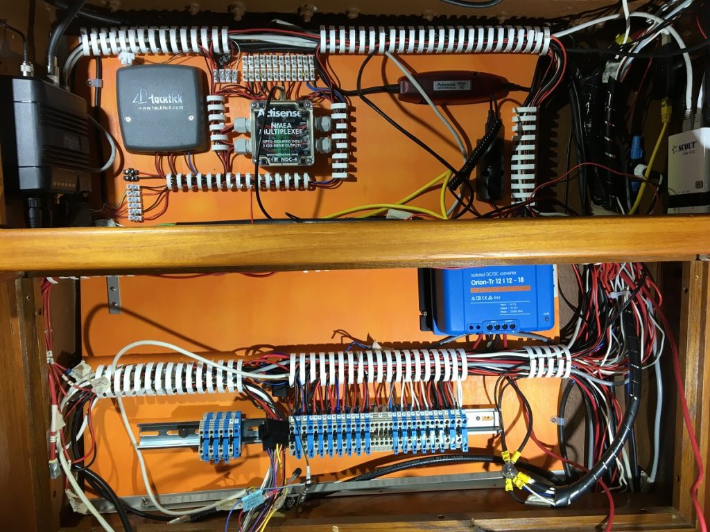
Of course, it is important here not to forget the new components, for which the cabling must also still be laid. A table in which all components, circuits and terminals are listed helps here.
3. Installation Frontpanel
First, a frame for holding the new front panel is attached approx. 8 cm further forward in the direction of the work surface.
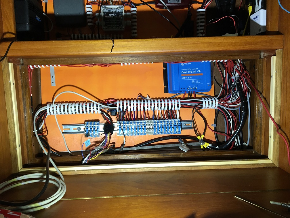
This provides more space to the rear of the control cabinet, which simplifies installation and wiring. The front panel is to be divided horizontally into two parts: a strip of approx. 7 cm is to be permanently installed in the upper area and partially covered by the 22 inch monitor. In the uncovered part the control unit for the fuel cell and the switches for cabinet light and Silent AIS mode shall be installed. The lower part of the panel, with a height of about 26 cm, is to be hinged to accommodate the radio, HiFi, circuit distributor, remote gas switch, heating control unit and fuel gauge components. A template is used to check whether the overall dimensions fit and the components are attached coherently.
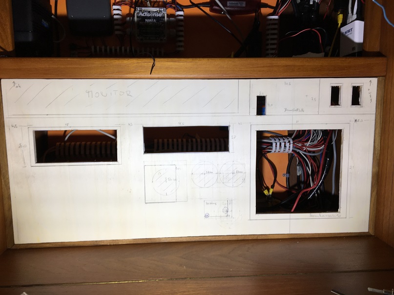
Mark and cut out cutouts for components and test fit. Cutting out is not without difficulty because boatbuilding plywood with teak veneer is scarce and quite expensive. Mistakes should be avoided if possible because replacement material is not readily available.
Paint the front panel. Attach closer and retaining mechanism, install components and interconnect. Holding mechanism should be easy to use but secure so that the front panel holds securely even in swell and uncomfortable conditions. Therefore, in addition to 2 brass snaps, a simple sash lock should also secure the panel.
The upper part of the front panel is fixed. Will later be covered for the most part by the monitor. In the right part the control unit for the fuel cell and the switches for AIS Silence and lighting in the navi control cabinet.
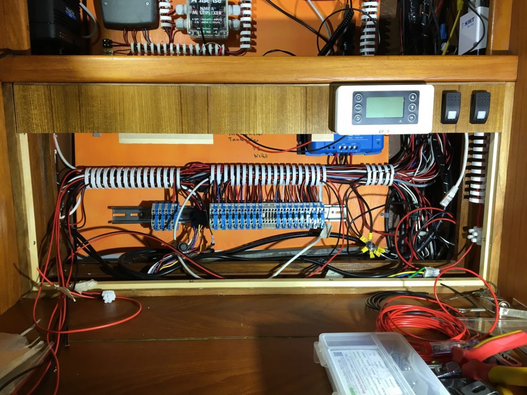
Lower part is removable to access the wiring of the components if necessary. On the front side are mounted VHF radio, HiFi, level indicator drinking water, remote gas switch, remote control heating and circuit distributor.
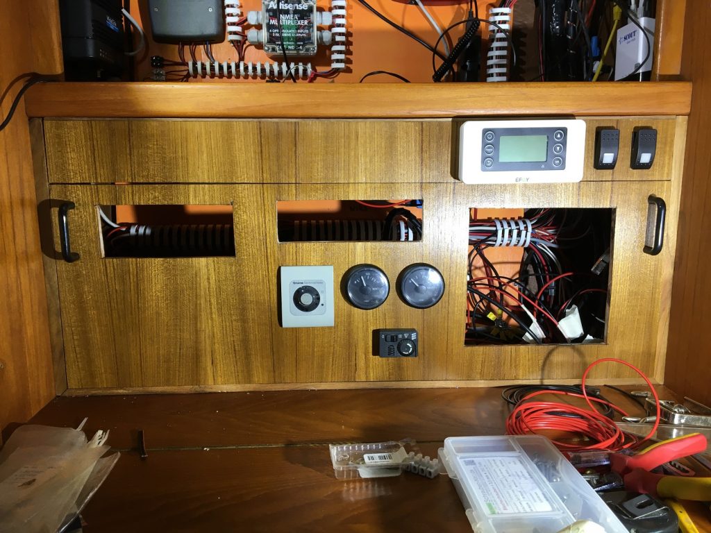
Now the large components switchboard, VHF radio and HiFi system are inserted and fixed.
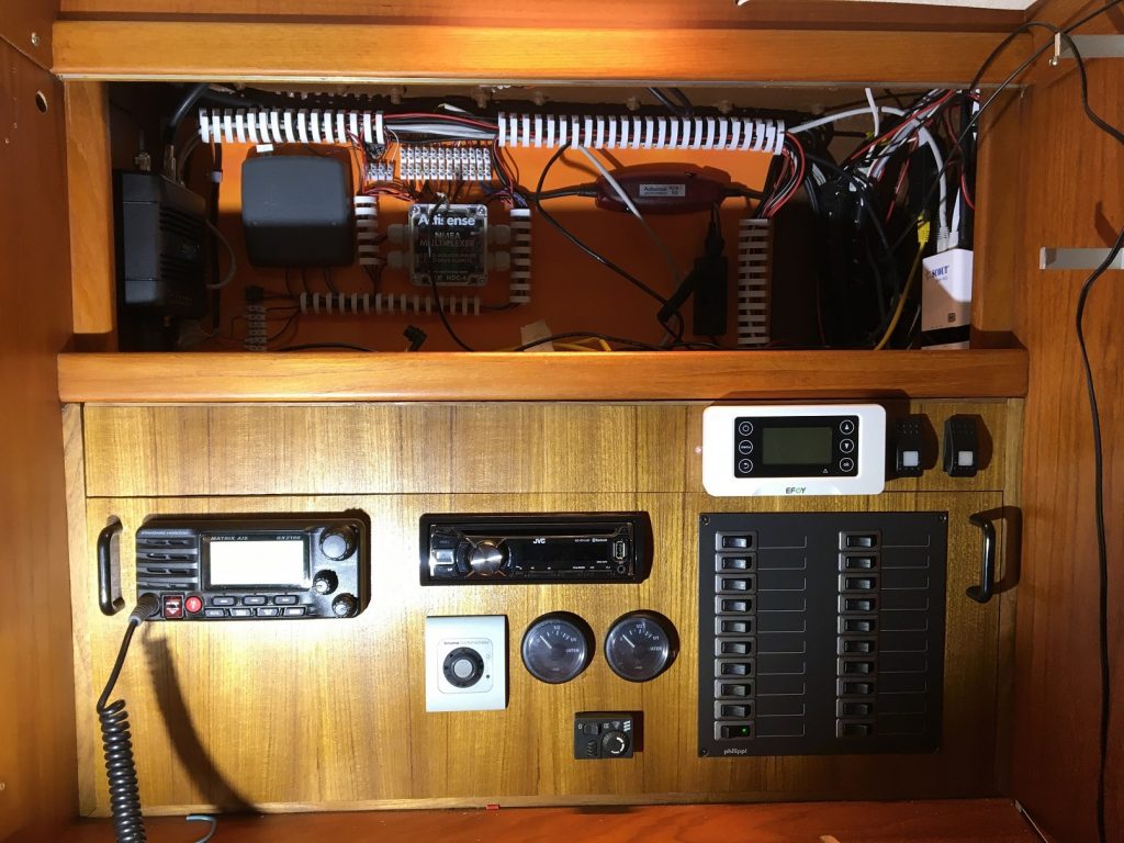
Then fun also already times the monitor, in order to approach the planned final result times …
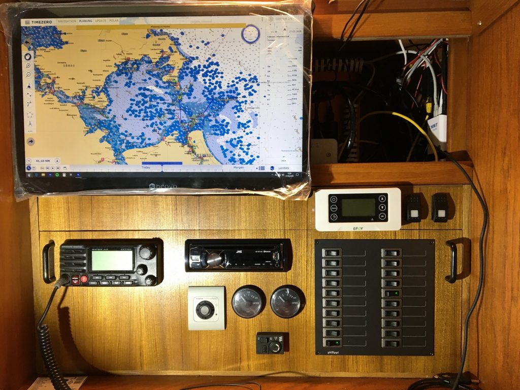
Installation drinking water level indicator. After much back and forth, I have now hopefully found a level indicator that fits the existing sender (4 – 20 mA) and procured a 2nd sender with display for the 2nd tank. Display on the Navi panel seems appropriate to me.
4. Installation and wiring of the circuit distributor
The circuit distributor is a switchboard of the STV 220 model series with 20 circuits, each equipped with 10 A thermal rocker circuit breakers. The entire vehicle electrical system is thus divided into 20 circuits, in each of which the loads are sensibly switched individually or bundled together. The relatively small-scale separation of the circuits increases safety in the event of a fault and allows a targeted troubleshooting procedure. The thermal switchability facilitates the step-by-step exclusion of potential fault sources.
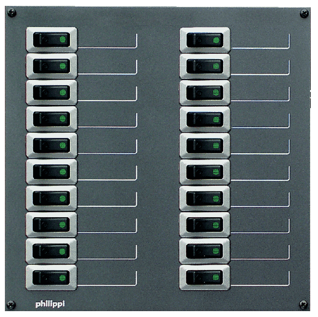
One half of the circuit distributor (10 circuits) is fed directly from the consumer battery and the other half (another 10 circuits) is fed indirectly from the consumer battery via a DC – DC voltage converter (Victron Energy Orion TR voltage converter 12V->12V with 220W).
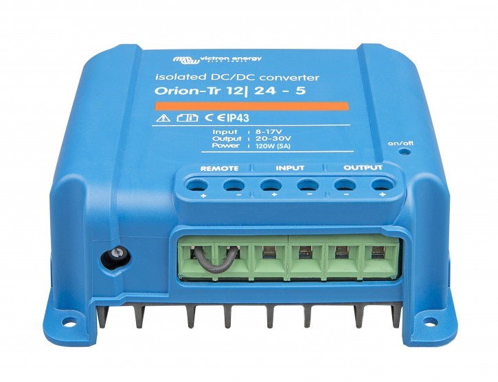
The technically simple consumers, which are rather insensitive to voltage fluctuations, such as interior lighting, navigation lights, refrigerator, etc., are connected to the directly supplied group, while the more sensitive navigation electronics such as on-board computer, AIS, GPS, autopilot, NMEA distributor, echo sounder and all other instruments are connected to the indirectly supplied group, for which a voltage of 12.5 V is permanently ensured via the voltage converter.
The background for this measure is the unpleasant experience that the regulator of the alternator had once been damaged on the road and in the following longer trip under engine fed a fluctuating, up to 16 V high voltage into the on-board network. This remained unnoticed for several hours. The depth sounder went crazy and at times showed completely nonsensical values and sent depth alarms. Then, while troubleshooting, more or less by accident, the message from the remote control of the fuel cell about too high voltage in the on-board power supply caught my eye. Until I would have had the idea to measure the on-board voltage during the troubleshooting, that could have taken some time. Fortunately, only the encoder from the depth sounder went out, but much more expensive electronics could have been destroyed if the error had not been noticed in time. Who routinely checks the on-board voltage while underway, especially when the engine is running? 😉
With the components installed and connected, it looks like this:
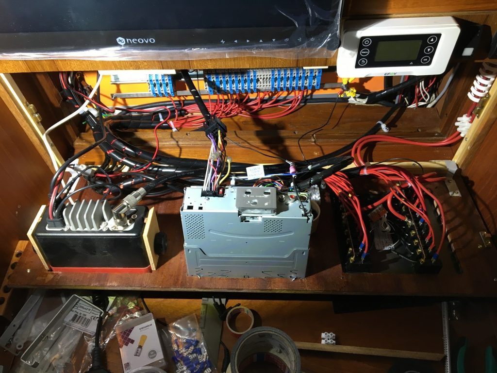
Heater and bilge pumps are on their own circuit panel closer to the consumer battery.
5. NMEA Data Distribution
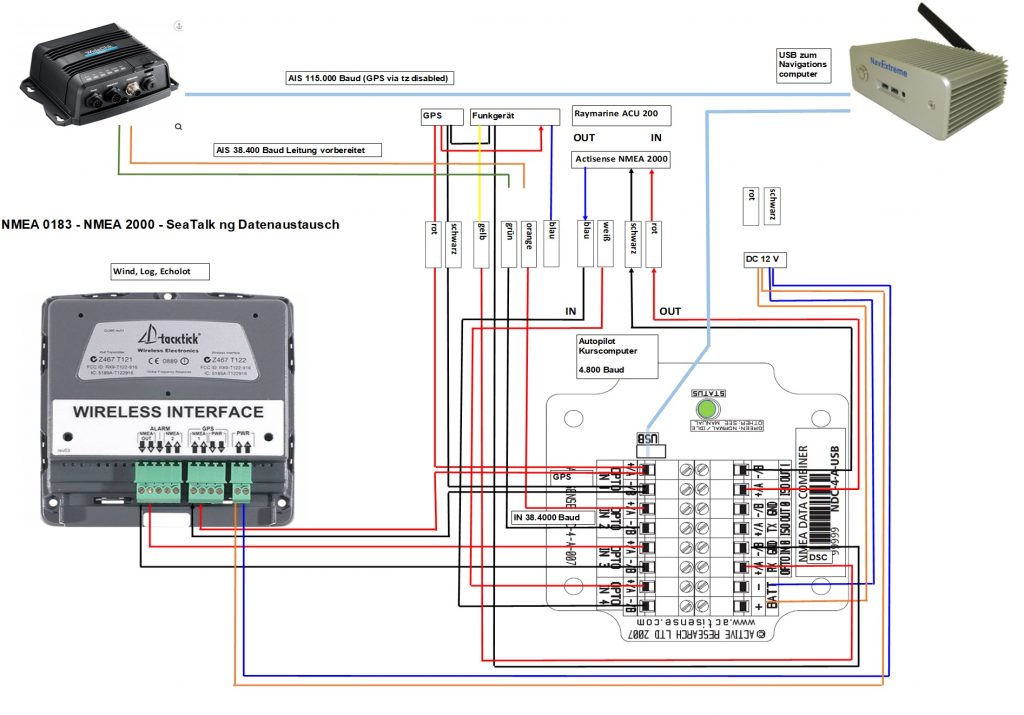
The upper part of the control cabinet houses AIS, GPS, LAN, WLAN, as well as the NMEA distribution. Looks complicated at first glance, but technically it is just the exchange of data in NMEA 0183 and NMEA 2000 as well as in the proprietary Raymarine format SeaTalkNG between the components AIS, radio, GPS, echo sounder, log, wind and autopilot. The data rate or bandwidth of the components differs significantly and ranges from 4,800 baud in NMEA 0183 to 250 kbit/s in SeaTalk NG.
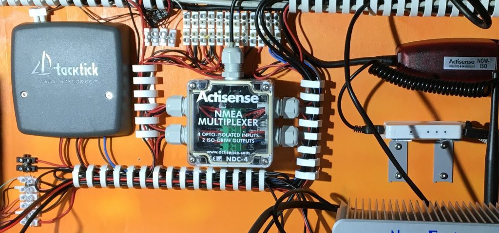
No question, a uniform format for the exchange between all components best on a NMEA 2000 bus system would certainly be the constellation of choice. But as it is when you have bought a 20-year-old ship: you don’t have the money to renew all the electronics in one go, you buy bit by bit what is needed and/or needs to be replaced. In 2011, there were no communication-capable devices on board at all. First purchases after the purchase of the ship were an AIS capable radio, a GPS and a year later then a TackTick instrument set with log, echo sounder and a wireless wind transducer, all with NMEA 0183. The existing wheel pilot did not yet have an NMEA data interface, but seemed to still do its job and was therefore allowed to stay for now.
For the connection of the components the NDC-4 NMEA Multiplexer from Actisense was the best choice, because it has a NMEA input with 38.400 bps for the AIS data and also a bidirectional USB interface to the computer, at that time a laptop, so that the data can be displayed in the electronic nautical chart on the computer.
It did not take long until the wheel pilot gave up due to permanent overload and had to be replaced in 2014 by a Raymarine autopilot with EV sensor, ACU 200 control and a powerful linear drive by means of quadrants from Jefa directly on the rudder shaft. Works perfectly in all positions I have experienced so far. An investment I have never regretted. But this now required the connection of SeaTalk NG to the NMEA multiplexer, which was done with an Actisense NGW-1 NMEA 2000 gateway plus SeaTalkNG to NMEA 2000 adapter cable to allow bidirectional exchange of the autopilot with the already existing components.

In the technical principle diagram, the configuration for data exchange between the components is as follows:
Postscript from July 2020:
So, now I have given in to my urge for perfection and once again reached into my pocket. The two NMEA2000 and SeaTalk NG capable components, the AIS Transponer and the Raymarine autopilot, I have now connected via an NMEA2000 backbone to an N2K capable multiplexer.
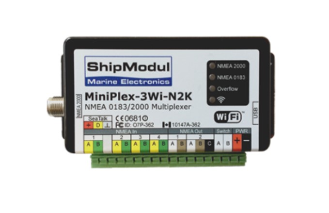
The old Actisense components NMEA 0183 multiplexer and NMEA 2000 converter I have taken out. The problem with the old constellation was simply the bottleneck in the conversion of NMEA 2000 / 0183. In the new constellation, the high NMEA 2000 data throughput is retained when passing via USB to and from the computer, because no conversion to NMEA 0183 must take place.
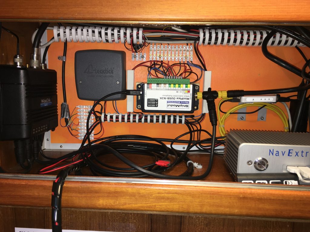
This makes for a much clearer look.
And this is how the simplified and optimized installation now looks in the principle diagram:
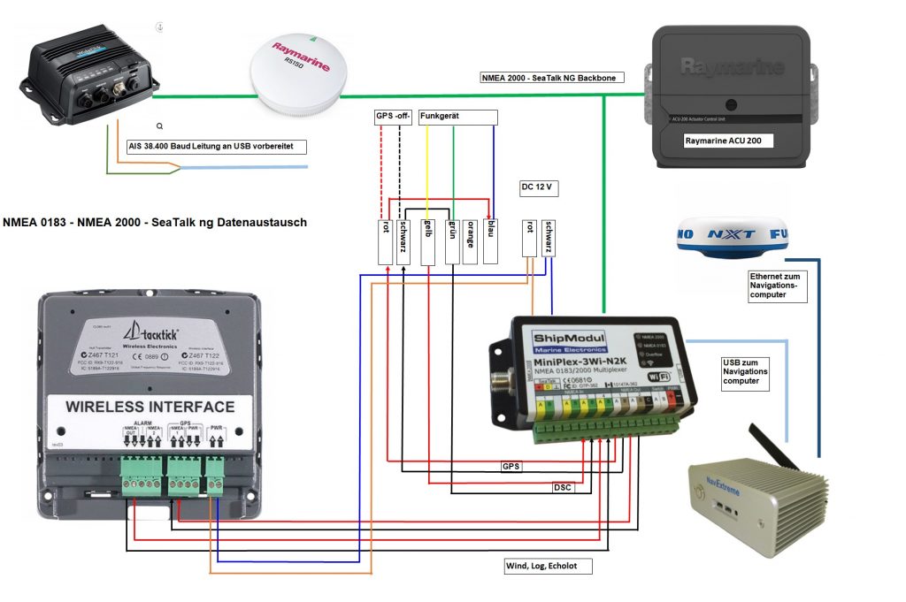
Fazit:
It is a good feeling to have finally completed this elaborate work that had been postponed for years. In view of the total of between 60 and 80 hours of work and the many small and large purchases that were necessary, the result may seem modest at first glance. You can hardly see or feel it in everyday life when everything works as desired. But it’s better than the other way around. Nothing is more annoying and dangerous on board if the electrical system does not function reliably and cleanly and you have to keep troubleshooting. The most noticeable positive aspects in everyday life are that there is no longer a laptop blocking the chart table and that the main consumers can be switched separately from each other.

Moin,
Respekt, super geplant und umgesetzt. Ich bin auch dabei, bzw. in der Planung meine Schalttafel auf Vordermann zu bringen. Sieht auch recht wüst aus. Welche Klemmentypen hast du denn genommen ? phönix? Und wenn ja, wo hast du die bestellt?
Liebe Grüße
Bernd
Moin Bernd, habe Weidmüller Reihenklemmen verwendet und ohne große Recherche bei SVB bestellt. Viele Grüße Alex
Supi, vielen Dank
Grüße
Bernd
Mir schwirrt der Kopf – aber Du bis ja Profi !
Nein, kein Profi, nur begeisterter Dilettant und Bastler. Die Winter sind lang und es macht halt auch Spaß, wenn im Sommer unterwegs alles funktioniert.
Hallo,
Lüsterklemmen in der Bordverschaltung würde ich vermeiden. Was die Empfindlichkeit der Bordelektronik angeht, sind selbest meine alten Autohelminstrumente alle schon intern mit einem Spannungswandler versehen und können somit ohne weiteres in einem 24 V Bordsystem verbaut werden. Eine Überspannung der Lichtmaschine war bestimmt nicht die Ursache für den Ausstieg deines Echolotes eher ungezügelte Störspannungen durch einen defekten Lichtmaschinenregler. LG Herbert SY Birdy
Hallo Herbert, guter Hinweis. Viele Grüße, Alex