
Step by step description:
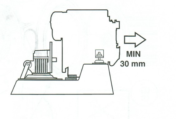
Room to move: to be able to separate the Saildrive from the machine, both components must be pulled apart by about 5 – 6 cm
I didn’t want to do it the way Chris showed in his really great video, by pushing the engine forward with a lever on previously placed wooden parts. The engine alone without Saildrive weighs at least 150 kilos and there is hardly enough space in the engine room to put a lever or something underneath..
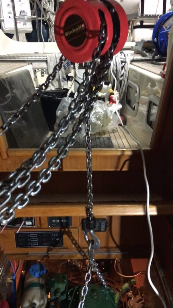
Instead, I bought a simple chain hoist for 40 € to hang the engine and thus be able to move the necessary centimeters controlled and without much effort. The engine is right under the companionway and so I was able to attach the chain hoist to a beam above the companionway easily and yet safely. From the aft cabin, there is good access to the saildrive and the rear of the engine when the cover is removed. There is sufficient freedom of movement for the engine: lines and cables are long enough everywhere, there is enough space to lift the engine a few centimeters and pull it forward
.
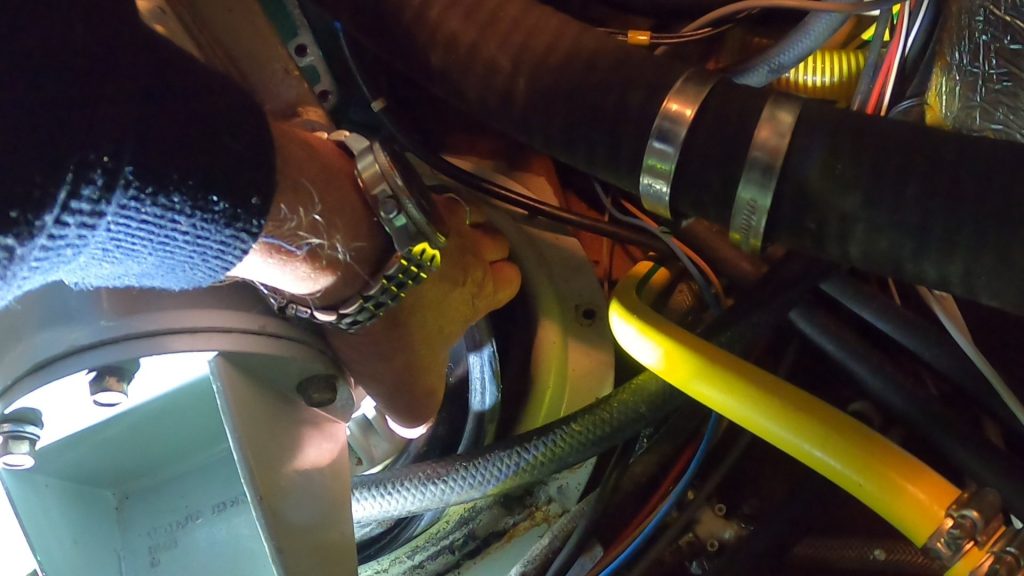
Prepare Saildrive: the shift cable to the gearbox and the cooling water hose must be removed
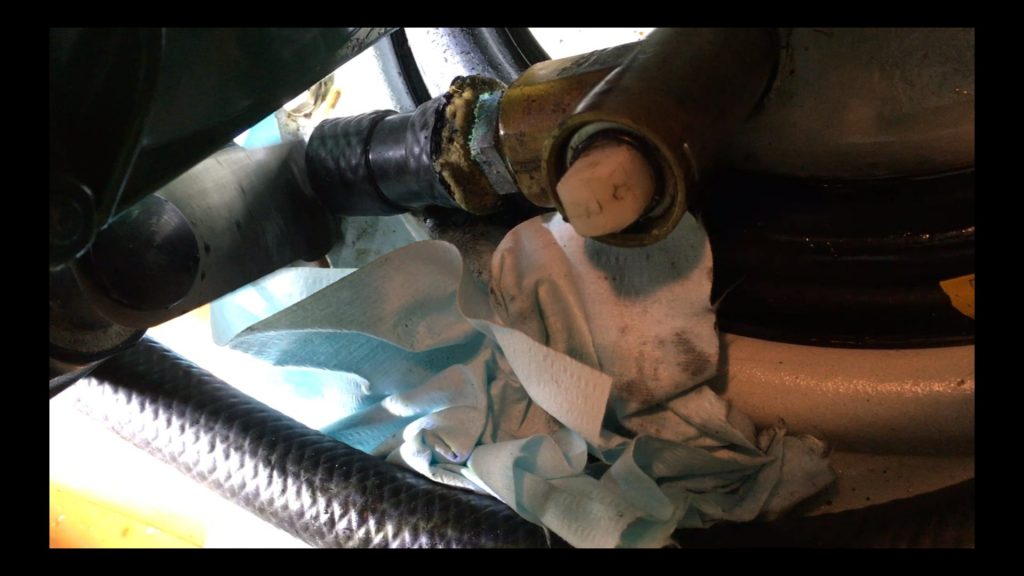
Then drain the gear oil, not forgetting to pull the dipstick. And the propeller must be disassembled so that the saildrive will later fit through the relatively narrow fuselage opening when it is removed..
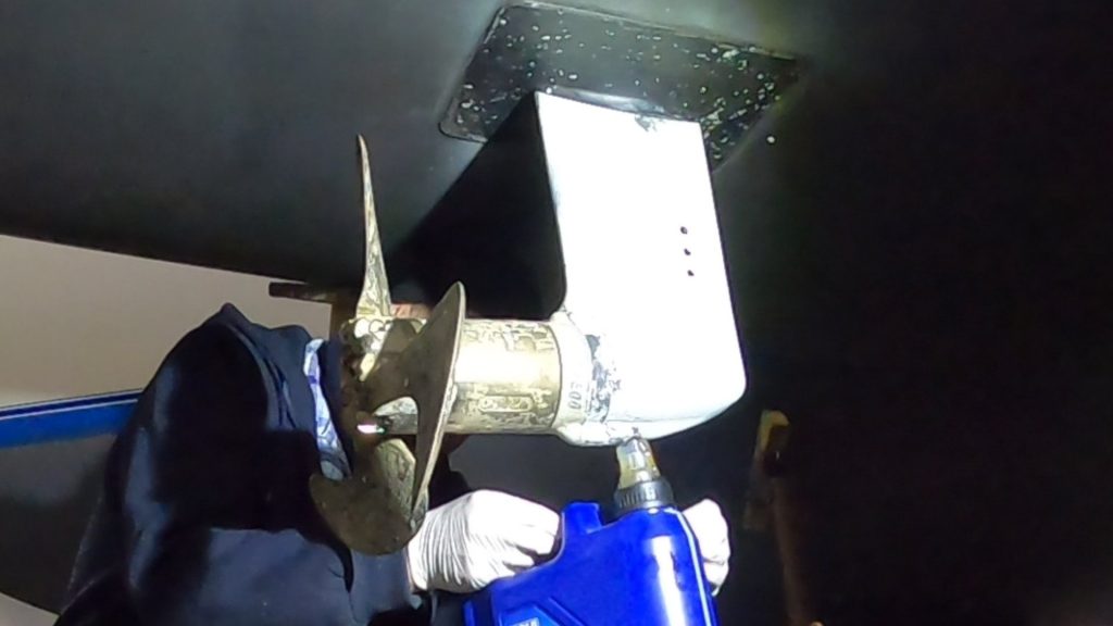
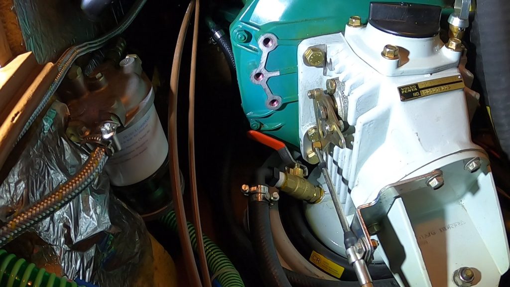
I left the exhaust hose because I would not have gotten it off without destroying it and besides, there was enough room.
Then you still have to remove the saildrive collar on the hull. A replacement boot is included in the Volvo Penta spare parts kit if you do not want to reuse the old boot.
Hanging up the engine: the next step is to hang up the engine. A strong beam – laid across the companionway – provides the upper attachment for the chain hoist. The higher the chain hoist can be attached, the better, because this keeps the tipping angle as small as possible when the engine is later pulled forward. It is also important that the 3 attachment points on the engine are distributed in such a way that the engine hangs securely and well balanced and can be pulled upwards as straight as possible. The whole thing is a bit tricky because the engine is only on 2 attachment points at the front, but is attached to the Saildrive at the rear and is thus supported to the rear via the Saildrive.
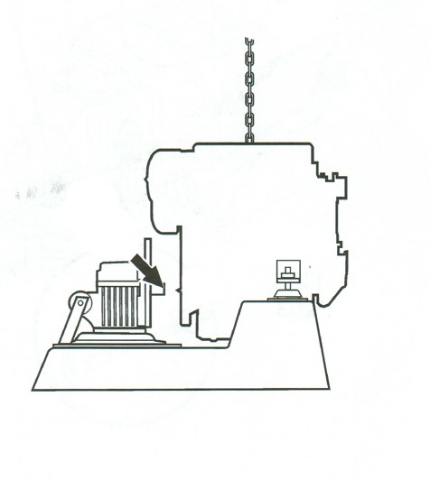
When you loosen the attachment between the Saildrive and the engine, the rear support for the engine is missing and therefore it must be suspended at this time in such a way that it does not change its position after being detached from the Saildrive. For a first test, loosen the bolts of the front suspension and lift the engine about 1 cm, also to see if it goes straight up at least in the lateral alignment.
Now all bolts for the front feet are taken out. Caution: if the upper attachment point is not exactly centered above (the center of gravity of) the engine, gravity will move the engine toward the center of gravity when the bolts are loosened. If this movement is too extreme, the engine must be lowered again and the upper attachment point readjusted accordingly. As a result, the engine will hang freely and about 1 – 2 cm above its old position.
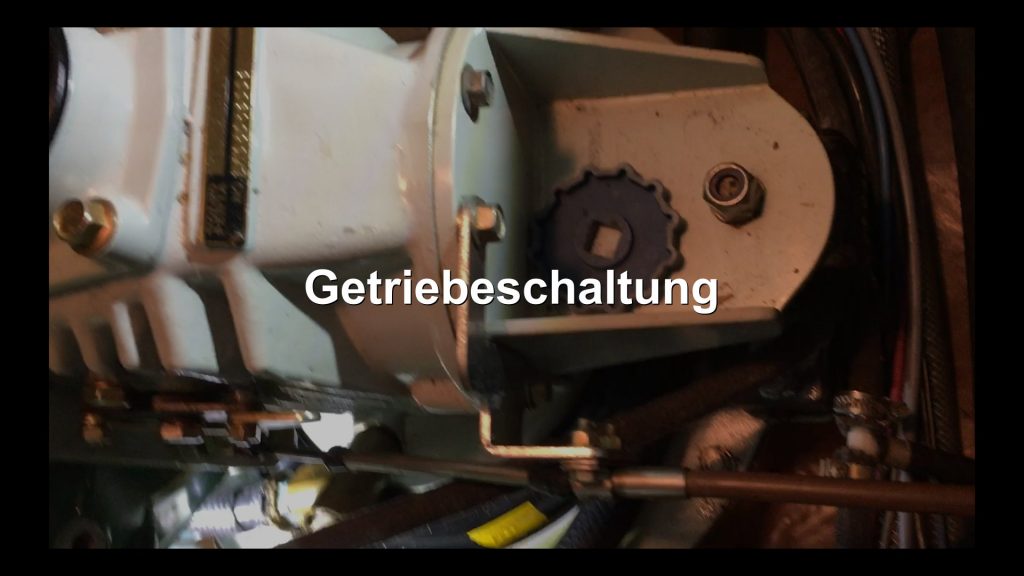
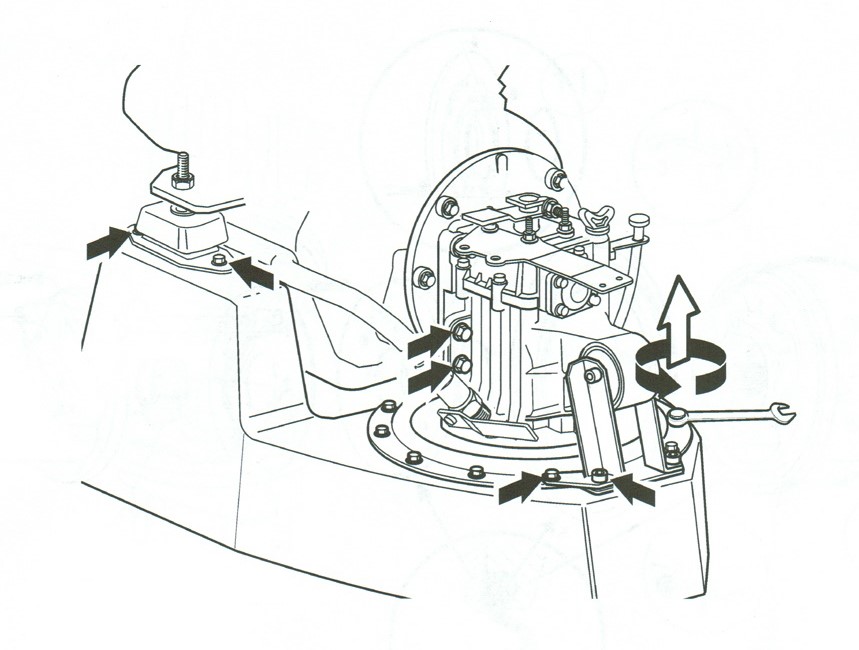
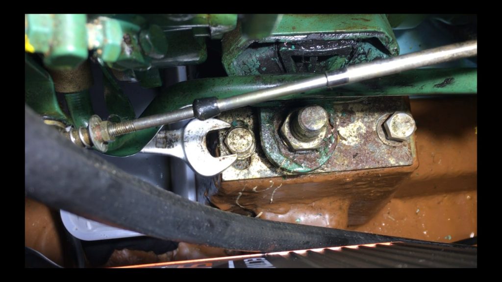
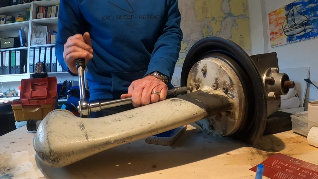
Separate the engine and the saildrive: Now loosen the 6 bolts that hold the Saildrive gearbox to the engine.
However, the loosened bolts still remain in their threads with a few turns to prevent uncontrolled sagging of the machine during separation, should the suspension not be neatly balanced.
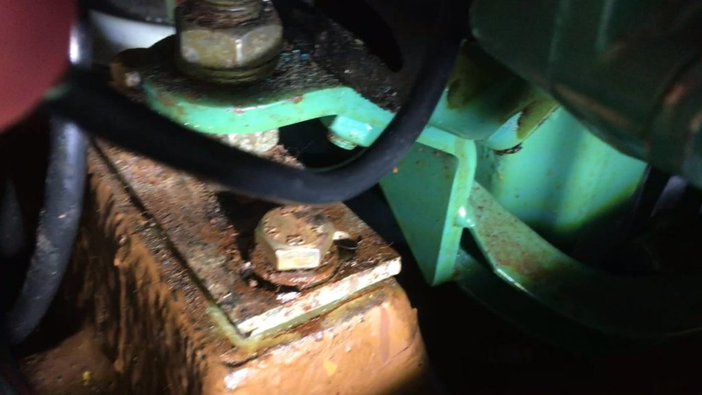
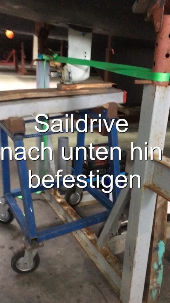
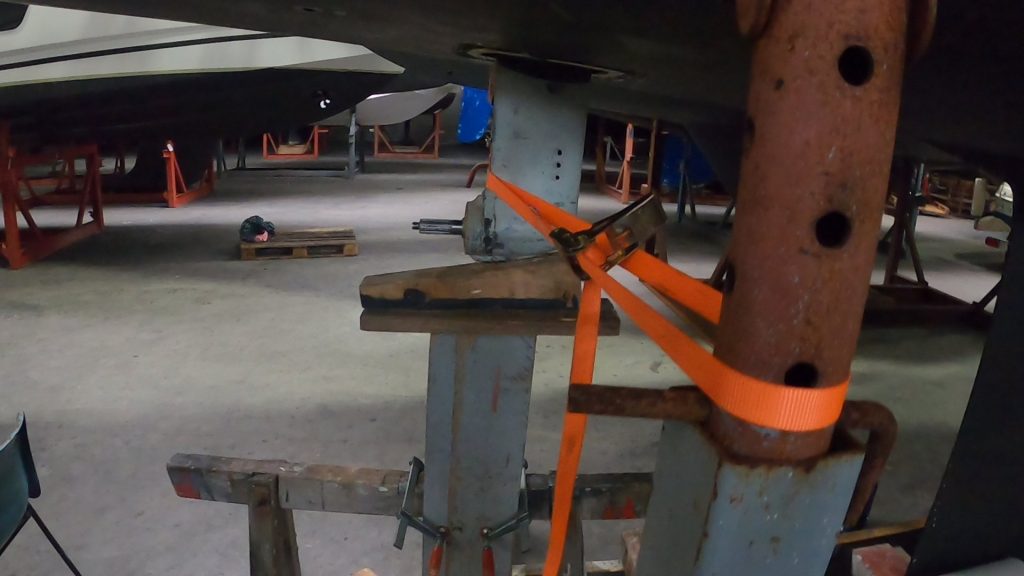
Also, the bolts for the outer diaphragm retaining ring of the saidrive remain tight to hold the saidrive when engine is later pulled forward (picture left).
In addition, the saildrive is secured on the outside under the fuselage with straps and supported by a trestle from below to hold it in place for deployment (picture right).
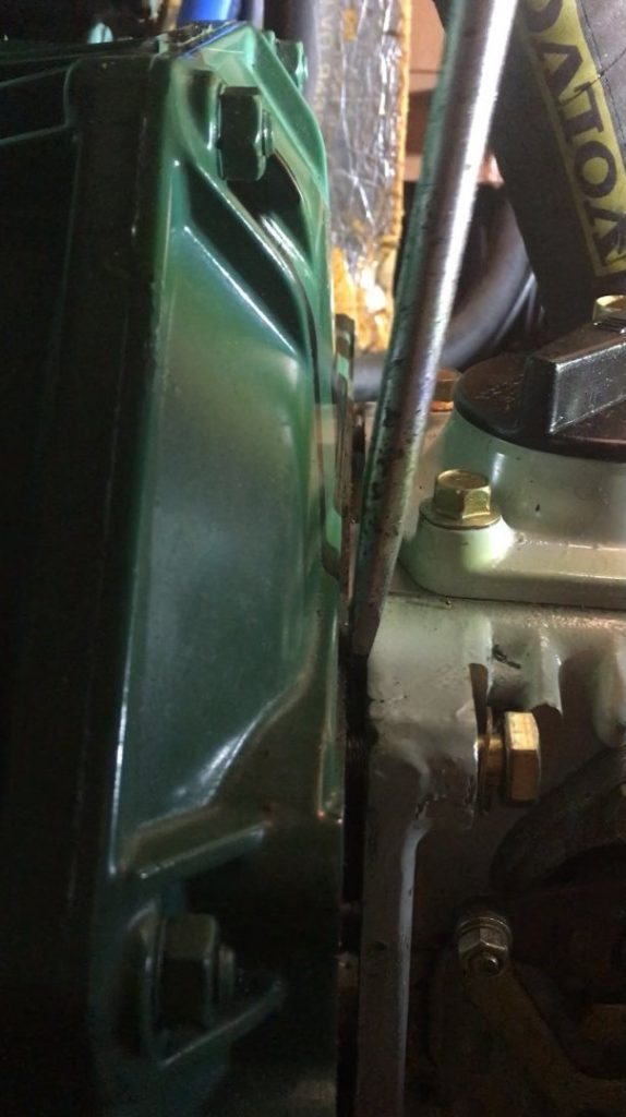
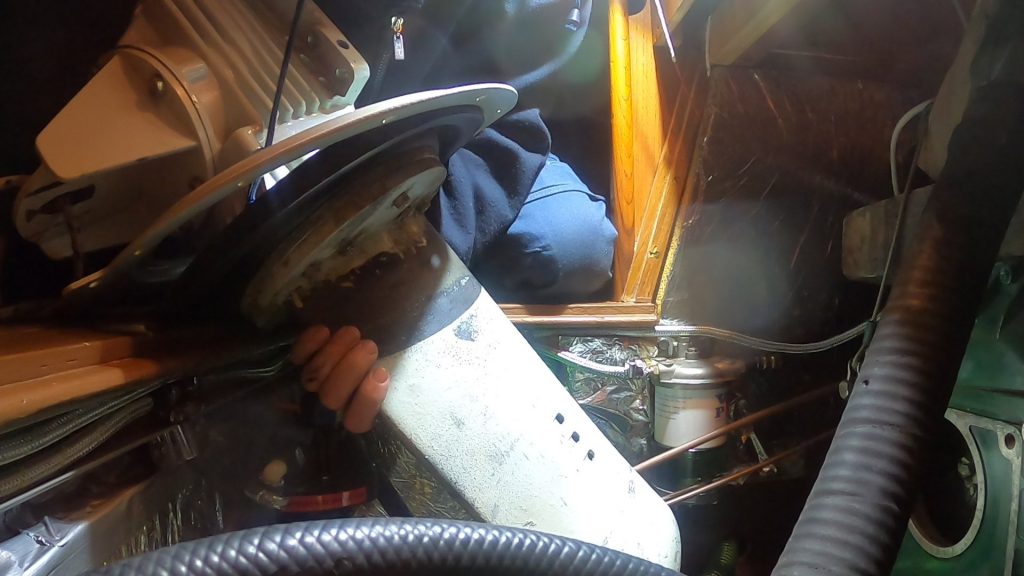
Now place a large screwdriver between the engine and the Saildrive and carefully press them apart alternately from the left and from the right until there is a gap of approx. 1 cm between them. (Picture left)
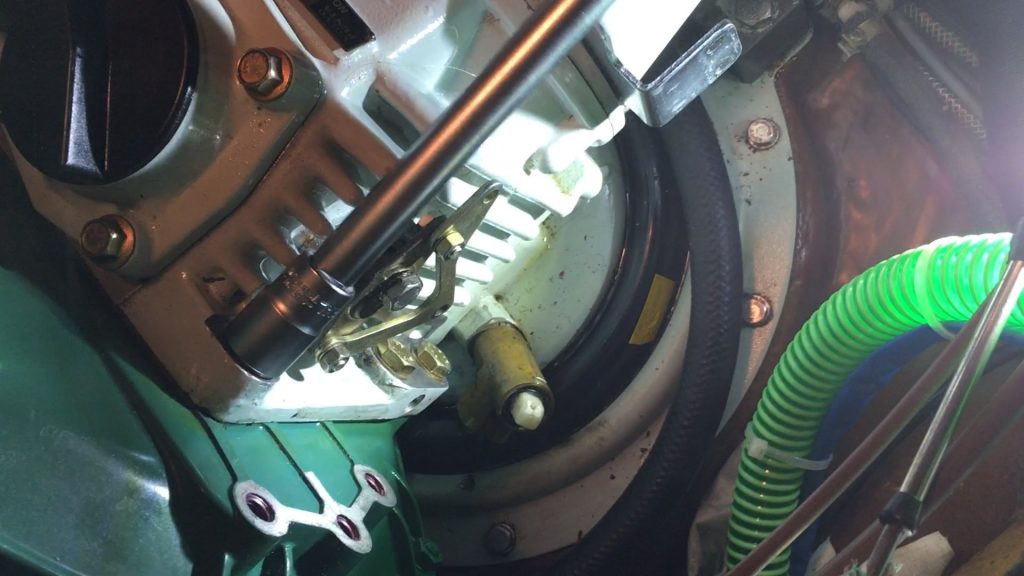
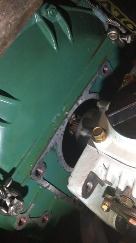
Now you can also see clearly whether the rear part of the engine wants to sag downwards. A suitable piece of wood under the engine can now be used as an additional safety measure to prevent uncontrolled sagging of the engine when it is pulled apart further. Then the 6 fastening bolts that have already been loosened are taken out completely. Now the engine is pulled forward about 5 cm with a rope until the shaft of the Saildrive has come out of the counterpart in the engine. (Picture on the right)
The engine is now to be fixed in this position.
Remove the Saildrive: the Saildrive now stands alone on the diaphragm, the lower support and the rear bolts.
These and the bolts for the outer diaphragm retaining ring are now all removed. After this, the saildrive only rests on the diaphragm, the outer circlip lies loosely on the diaphragm and the saildrive can be lifted up as a whole. Before it can be lifted out completely, the outer circlip must be pulled down over the diaphragm, otherwise the whole thing would be too bulky to lift out.
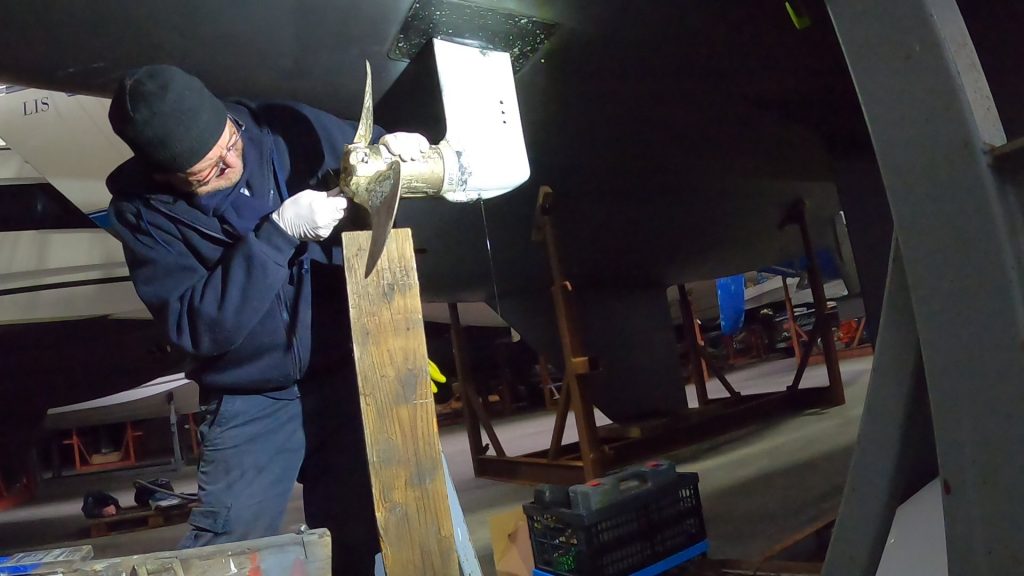
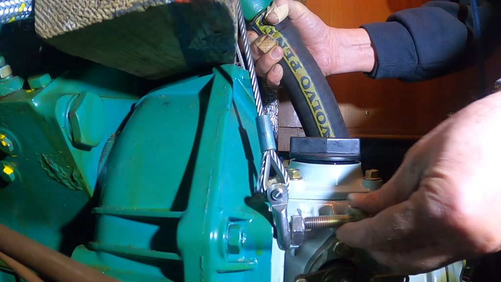
Then the Saildrive is lifted upwards as a whole and tilted slightly backwards in the process.

This requires some force, because the part weighs about 26 kg. Since the opening for the saildrive is very narrow, at least in my case, you have to thread the saildrive upwards with a little patience. Attention: when putting down the saildrive, make sure that all openings to the gearbox (filler hole, oil dipstick, oil drain plug) are closed, because despite draining, there is still some oil inside that can leak out.
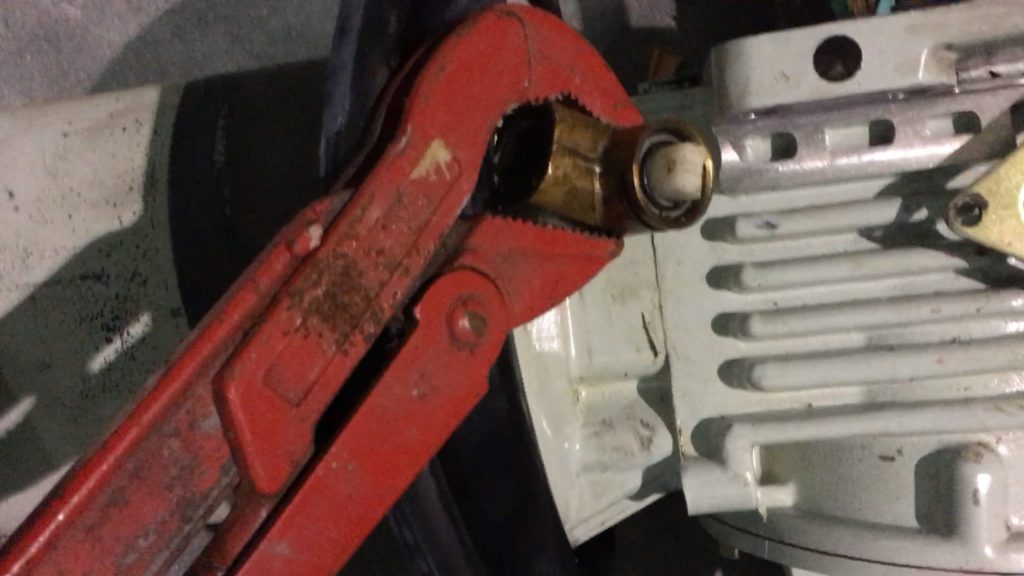
Disassemble and clean the saildrive: First, remove the old seacock.
Then the saildrive shaft is separated from the lower part of the gear unit. To do this, loosen the total of 10 Allen screws (6mm) and unscrew them. The middle screws are secured with wire, which must be removed beforehand.
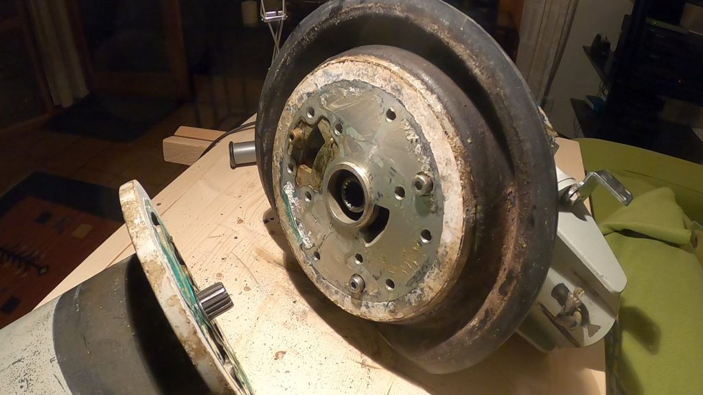
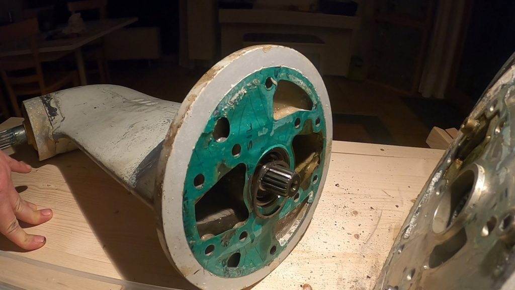
Strictly speaking, the lower part of the gearbox consists of an aluminum plate, which in turn is attached to the gearbox housing with 3 screws and thus simultaneously holds the rubber diaphragm, whose replacement is the actual goal of the action. The connection between the shaft and the gearbox is sealed at this point by a paper gasket, large parts of which can be easily detached from the metal.
Only in the outer area and on the inner channels has the seal suffered in part and must be laboriously scrubbed off together with lime or oil residues, otherwise it can be removed easily and intact. The surfaces on which the new seal and diaphragm are to be placed must of course be smooth and free of residue after cleaning so that the seal and diaphragm can function properly. Small shock in between: it seems like the bearing housing cover is cracked and needs to be replaced.
But careful sanding shows that it is casting flash residue, which disappears completely after sanding. Great relief.
Condition of the membrane: there are – after more than 30 years of use – no signs of wear or weathering, the rubber is really thick and strong and – at least felt – just as flexible and elastic as the new membrane. At most, the surface is calcified and overgrown and a little shriveled in the areas that were wetted by water in the long term.
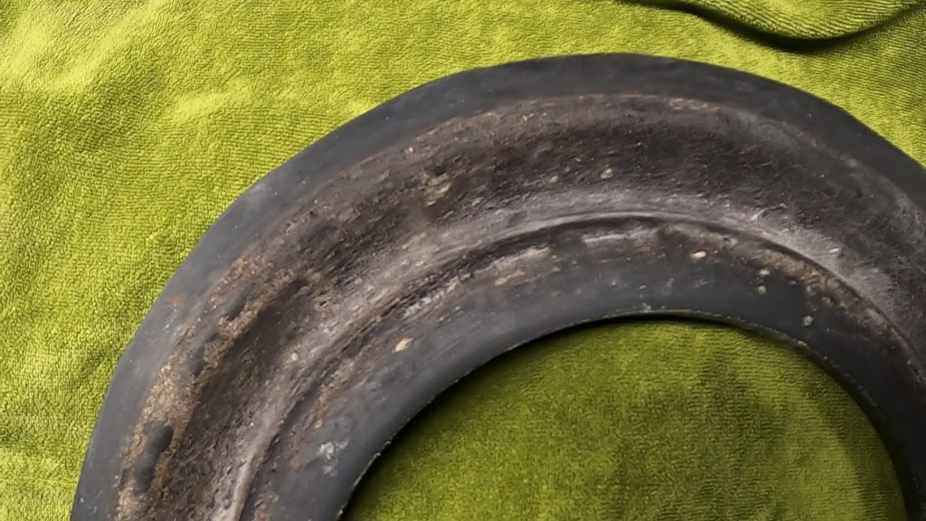
Otherwise, there were neither mechanical nor chemical stresses during the time of use, at most a little oil or diesel from above and seawater from below. In this respect, the replacement was only worthwhile because I could not have replaced the old seacock without removing the saildrive.
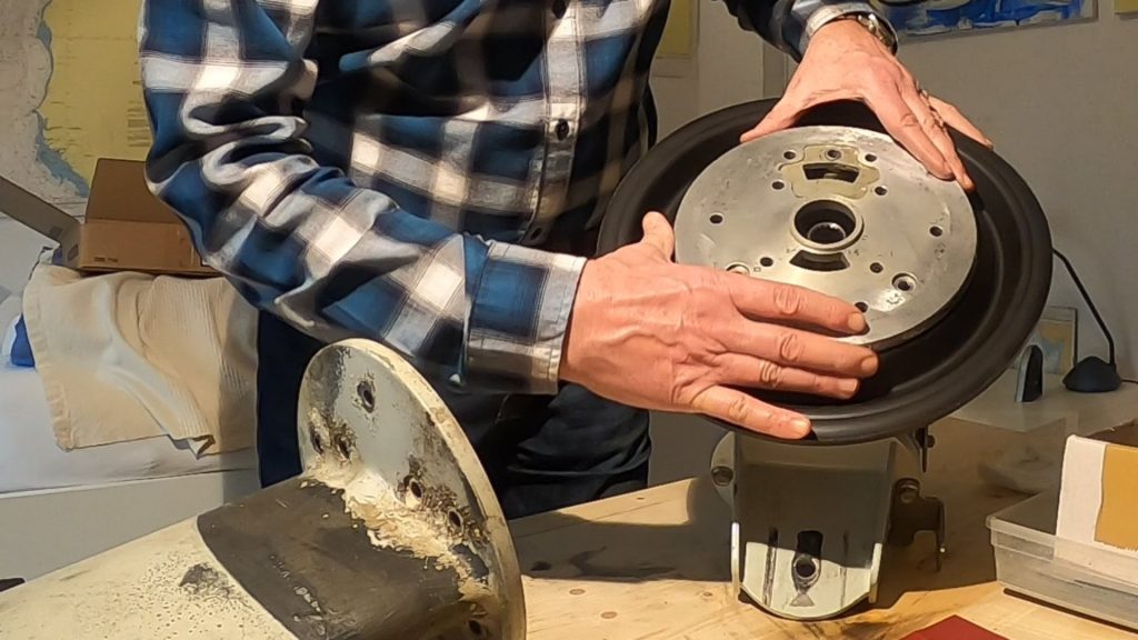
Installing diaphragm and reassembling gearbox and shaft: the reassembly is relatively easy if everything is well prepared: all parts are cleaned and rubber diaphragm, paper gasket, O-ring, all screws and torque wrench (10 – 25 Nm) are ready. First, the diaphragm is reattached to the gearbox housing
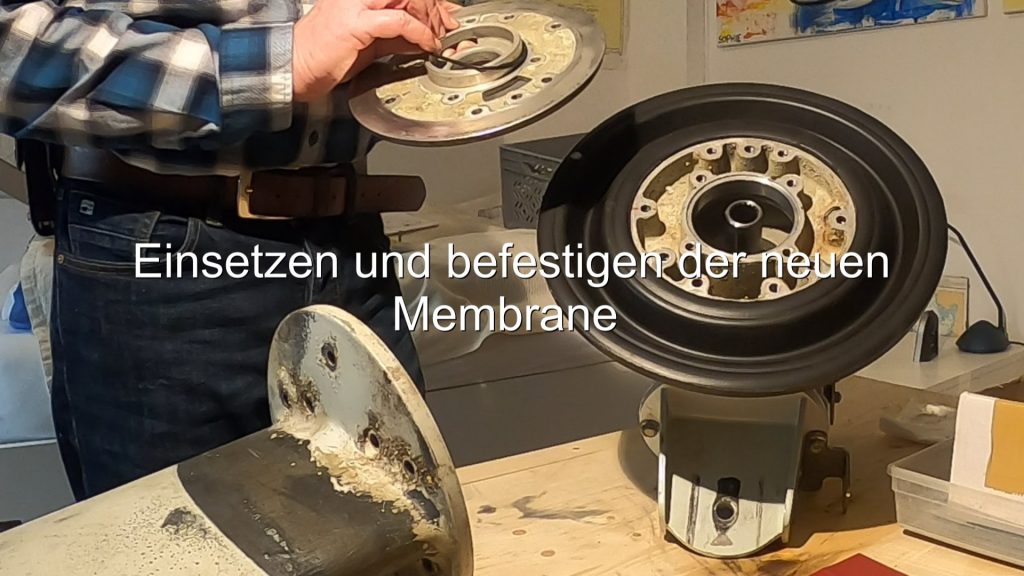
The required aluminum plate is screwed on with 3 Allen screws (6mm, 26 Nm). The shaft for the drive shaft gets a new O-ring from the Volvo Penta Service Kit..
The shaft is then fastened to the gearbox housing with a total of 10 Allen screws (6mm, first 10, then 25 Nm). When assembling, make sure that the paper seal is in its correct position and that the very thin spacer rings in the shaft for the drive shaft are correctly in position. The sequence and torque for the screws are exactly specified.
After tightening, the 4 innermost screws are connected with wire to secure them. The new seacock is not yet attached to keep the Saildrive as slim as possible before reassembly.
Preparation and reassembly: Lift the engine slightly and pull it forward by approx. 5 cm. Clean the base. Pull the ring over the diaphragm. Lower the saildrive into the shaft from above, tilting it back slightly until it passes through the opening to the outside.
Now lower slowly until it comes to rest on the rubber diaphragm. Fix the rear stand and tighten the bolts by hand. Now support the saildrive from the outside at the bottom and align it using the tensioning strap so that it is approximately in its correct position.
Grease the head of the drive shaft and the mating piece well. Align the engine so that the drive shaft is positioned as exactly as possible opposite its mating piece. Now slowly pull the engine backwards, readjusting repeatedly if necessary. The back of the engine and the front of the Saildrive must be exactly flat against each other so that the head of the drive shaft can engage in its mating piece. To overcome the last centimeter, a little jerking and turning the Saildrive back and forth helps. Now tighten the 6 bolts that connect the saildrive to the engine with 40 Nm.
The engine is now supported to the rear via the Saildrive. Fine adjustment is then made for the front feet, which are also screwed back on with 40 Nm. The engine and saildrive are now firmly supported as a unit on their abutment. Screw on the holder for the rubber diaphragm with 20 Nm. Insert new seacock and fasten cooling water hose. Reinstall the shift cable.
Conclusion: I thought back and forth for a long time about whether I should really go to the trouble. If it wasn’t for the exchange of the old seacock, I probably wouldn’t have done it.
Overall, I expected more difficulties. With regard to the following 3 aspects, I was unsure: the safe and controlled movement of the engine, the maneuvering of the Saildrive out of the engine compartment and the remarriage of Saildrive and engine.
For moving the engine, the wire rope hoist was a very good and easy to use solution. Moving the saildrive out was easier than expected, especially because there was enough space available. The “remarriage” of saildrive and engine was a bit tricky and requires strength and dexterity, but this was no problem with the hanging engine and the pre-fixed saildrive.
In total, I have invested (as a non-expert) about 20 h of work (pure execution without preparation and thinking about solutions) and am satisfied with the result. In retrospect, I am glad about the experience and that I now have a functioning seacock and certainty about the condition of the diaphragm.
Hallo
ein super Bericht, da muss ich leider auch noch ran… und auch gleich 2x , weil Cat
Was hast du für ein Seeventil genommen, bei meinen SD ist das nämlich auch defekt
Ahoi
Thomas
Hallo Thomas, danke für Deinen Kommentar. Für das Seeventil habe ich ein Kugelhahn 1/2″ Messing CR plus Doppelnippel genommen. Grüße Alex
Danke für die Anleitung. Das ist demnächst fällig.
cool! Viel Erfolg!
Hi! Ich stehe gerade bei mir im Boot und wollte den Saildrive auch rausnehmen. Kann mir aber so gar nicht vorstellen, wie man die vordersten Bolzen des Manschettenrings festziehen sollte. Also die, die quasi unterm Motor sitzen. Beim Einbau kommt doch erst der Motor an den Saildirve, da ist wirklich kaum mehr Platz. Wie hast du das denn gemacht?
Für den Ausbau des Saildrives musst du den Motor ja aufhängen und für die Trennung von Motor und Saildrive etwas nach vorne ziehen. Nach dem Wiederzusammensetzen von Motor und Saildrive steht der Saildrive auf seinem hinteren Lagerpunkt und ist vorne am noch hängenden Motor fest. Jetzt senkst du das Ganze soweit ab, dass du die Membran Halterung anschrauben kannst. Dabei hängt der Motor vielleicht noch so 1-2 cm über seiner Endposition. Dann senkst du ihn ganz ab und machst die Feinjustierung. Hoffe das hilft und wünsche dir viel Erfolg!